Introduction to Digital Electronic Systems
Electronic
devices which work on digital principle are largely occupying an average home
nowadays. Digital electronics have intruded into almost every equipment which
are being used daily ranging from the wrist watch to automobile control system.
Therefore, designing and manufacturing of such complex systems have become a
popular industry.
Before digital
electronics catch up the place,
analog electronics was in widespread use. Analog systems
are based on a continuous voltage variation in which the system can generate
any voltage level within the given range. On the other hand, digital
systems use discrete
time and voltage levels to
represent signals. They are eventually coded into binary digits with two
logical levels, namely HIGH and LOW.
Advantages of Digital Systems over Analog Systems
- Immune to noise and errors
compared to analog
systems
- Can be designed easily
- Signals can be reproduced easily
- More reliable
- Production cost is cheaper
- System is faster
Logic states
There are only
two possible outcomes from a digital system. They are the voltage HIGH and
voltage LOW. These two levels can represent the states of a physical phenomenon
such as,
- whether a switch is opened or closed
- whether a signal is present or absent
- whether some event has happened or not
These logic states can be directly
mapped into the two states
of Boolean Logic* namely, TRUE and FALSE. Moreover, in order to perform arithmetic
operations, normally a ‘1’ is used for logic HIGH and a ‘0’ is used for logic
LOW.
Number system
Numbers are used to denote the amount of quantity of something. Historically, Humans have used many
types of number systems, a set of symbols used to indicate the amount, in
different time periods. For example, Babylonians used a number system with 60
different symbols. Moreover, the romans used their number system with several symbols, which have not used the concept of place value.
Hence, writing large numbers in roman system were cumbersome.
Nowadays, the decimal number system, which is using 10 symbols to indicate numbers is used widely. Originally developed by Indian mathematicians, who have introduced the symbol to denote nothing, which is ‘0’, the number system was mainly spread by Arabian traders to the
* Boolean logic will be covered later in this course
western world.
The symbol ‘0’ have allowed
the decimal system
to use the place value,
thus, making the writing easier.
The advent improvements in computer systems
have allowed the complex
calculations to be made through them. A problem arose
when denoting numbers in computer systems. Because, a computer, which is an
electronic device, uses voltage states to denote numbers. Since, there
are only two states as described earlier,
decimal number system
cannot be used with computers. Therefore, Binary
number system was introduced in digital domain.
Binary Number System
The binary number system uses only two symbols to represent a number. The symbols are 0 and 1.

In order to avoid the confusion between number systems, normally a subscript is used to distinguish them. The subscript is called the Base of the number system. For example,

Conversion between Decimal and Binary Number Systems
The same quantity
can be represented in various number system formats. It will be useful to understand how to change the base of
the number.
In order to convert a decimal number into binary form, the decimal number should be long divided by two and the residue in each division stage should be accumulated to create its binary form.


Octal and Hexadecimal number systems
Binary number
system needs so many bits to represent even a small quantity. Therefore,
analyzing the numerical states inside
a digital circuit
is difficult. This may create
head ache to computer programmers as well. Hence, different
number systems with easier conversion and notation methods were made.
The most popular number
systems within them are Octal and Hexadecimal number systems. Octal and Hexadecimal number
systems are using the base of 8 and
16 respectively. In order
to convert a
decimal number into either octal or hexadecimal, the same strategy of long
division can be used with small change in the divisor as 8 or 16 respectively.
The main
purpose of octal and hexadecimal systems are to provide a short hand notation
to binary numbers. Since, the bases of octal and hexadecimal number systems are
even multiples of the base of the binary
system, binary bits can be grouped together
and converted directly to and
from the octal and hexadecimal systems.
For the conversion between
binary and octal number systems,
binary bits should
be grouped into three bits.
Each group will be converted into its equivalent octal number system.
e.g.: 1101110111012 = 67358
110 111 011 101
6 7 3 5
For the
conversion between binary and hexadecimal number systems, binary bits should be
grouped into four bits.
Each group will be converted into its
equivalent hexadecimal number system.
e.g.: 1101110111012 = DDD16
1101 1101 1101
D D D
Binary arithmetic
Performing arithmetic operations in binary numbers is essentially the same as the operations in decimal systems. The concept of SUM and CARRY can be used with binary
numbers as well. Understanding the basics of binary
arithmetic will be helpful in making digital circuits. For example, digital
calculators using this principle to work with the inputs which are fed to the
calculator for the arithmetic operations.
Binary Addition
Binary numbers can be added using the long hand addition technique, which is normally used with decimal addition. A small difference between them is that, since the base is different, the most significant bit will be carried over to the next place value level and the least significant bit will be kept as the sum in the same place value level.

This is the basic operating principle in digital circuits which are used in various devices from a normal calculator to complex microprocessor of a computer. The implementation of Adder circuits will be covered later in the course.
Negative number representation
The concept
of negative numbers
was introduced to perform binary
subtraction. For example, consider the subtraction 5 – 3.
This is the same as 5 + (-3). Now, if some representation for negative binary
numbers was implemented, then, the subtraction could be done using the
same Adder
circuits used for addition. The problem here is how to represent (-) sign using
logic states.
Sign-Magnitude representation
The representation uses the left most bit as the bit reserved for indicating the sign. Hence, the MSB will be used for the sign and the rest would represent the magnitude. For example,

This method is
not best for representing negative numbers. It cannot be used for arithmetic
manipulation. Similarly, one entire bit is wasted for sign, thus, it is not an
efficient notation. Moreover, there can be two zeros in this system
and more care should be taken on choosing
the proper one.
2’s Complement representation
This is the
most popular method to represent negative numbers in digital systems. In this
system, positive numbers are represented as simple unsigned binary. For the
negative numbers, the representation is the number needed to make zero when the
positive number of same magnitude and the representation is added. For example,
-710 = 10012 where, the addition
of 1001 and 0111 is zero.
There is an easy way to determine the 2’s complement of a number. First, every bit of the binary number corresponding to the positive number is complemented. (This is called 1’s complement)

Then 1 is added to it.
10002 + 12 = 10012 = -71
This will give the 2’s complement representation of a negative number.
Arithmetic with 2’s complement
2’s complement can be directly used for calculations. For example, two numbers can be simply added to get the sum.


Logic gates and operation
Digital
systems are based on the manipulation of binary numbers. Therefore, some
physical circuits are needed
to store and manipulate binary
quantities. Logic gates provide the building
blocks for these complex circuit implementation.
There are three basic gate types and four derived gates. The basic gate types are
- AND gate
- OR gate
- NOT gate
AND gate
AND gate gives ‘1’ as its output when all the inputs are ‘1’. If at least one input is ‘0’ then the output will be ‘0’. The Figure and Table depict the symbol and the truth table of the two- input AND gate respectively.

Standard logic symbol of two input AND gate

The truth table for a two input AND gate
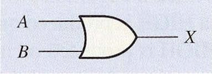
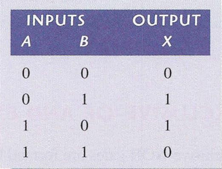
OR gate
OR gate gives ‘1’ as its output when at least one input is ‘1’. If all
the inputs are ‘0’ then the output will be ‘0’. The
Figure and Table depict
the symbol and the truth table
of the two- input OR gate respectively.

NOT gate
NOT gate inverts the input given to it. If ‘0’ is supplied to its input,
the output will be ‘1’. On the other hand, if ‘1’ is supplied, the output will
be ‘0’. The Figure and Table depict the symbol and the truth table of
the NOT gate respectively.
Note that, the NOT gate will always have one input.

Standard logic symbol of NOT gate

The truth table for a NOT gate
Apart from the basic gate types,
there are four derived gate types. They are,
- NAND
- NOR
- XOR
- XNOR
NAND gate
NAND gate gives ‘0’ as its output when all the inputs are ‘1’. If at least one input is ‘0’ then the output will be ‘1’. It can be thought of as a combination of AND and NOT gates. The Figure and Table depict the symbol and the truth table of the two-input NAND gate respectively.


NOR gate
NOR gate gives ‘1’ as its output
when all the inputs are ‘0’. If at least one input is ‘1’ then the output will be ‘0’. It can be thought of as a combination of OR and NOT gates.
Figure and Table depict the symbol and the truth table of
the two-input NOR gate respectively.


XOR gate
XOR gate gives ‘1’ as its
output when both inputs are different.
If they are same, then the output will be ‘0’. The Figure and Table depict the symbol and the truth table of the XOR gate respectively. Note that, the XOR gate will always have two inputs.

XNOR gate
XNOR gate gives ‘0’ as its output when both inputs are different. If they are the same, then the output will be ‘1’. It can be thought of as a combination of XOR and NOT gates. The Figure and Table depict the symbol and the truth table of the XOR gate respectively. Note that, the XOR gate will always have two inputs.


0 Comments